Kus Fuel Gauge Wiring Diagram
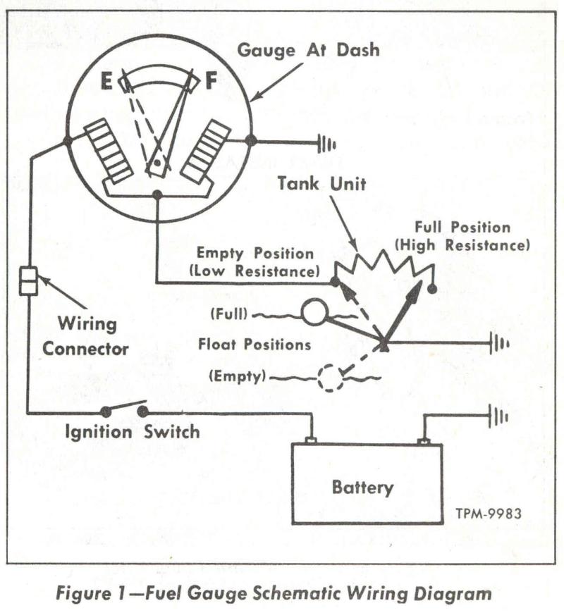
Gauge pointer should be at the position shown in the lower portion of the diagram. Empty the tanks of fuel & fumes before continuing with installation.
Fuel Gauge Wiring Diagram Searay
These instructions are for vdo gauges and accessories only.

Kus fuel gauge wiring diagram. Kus exports its products worldwide, mostly to europe and united states. Onnect the other end of the wire to the connection post on the back of the gauge marked "s". Vdo has tried to answer most of your questions regarding installation and trouble note:
Read the fuel level tank sender instructions and install the sender. 9 5 4 1 2 7 0 • w e m a u s a. This gauge is suitable for 12 or 24volt systems (a drop resistor is included for 24v systems) and is easy to install.
A wiring diagram is a simplified traditional. Each component should be placed and connected with other parts in specific way. Only connect cables according to the electrical wiring diagram.
Works with connect wires according to wiring diagram. With the black wire disconnected turn the 12 vdc power to the gauge on. No electrical components are inside the tank and exposed to fuel.
Most times, the wiring is bad. Gauge to sender connection 5. See your owner's manual for the location and go to next page for diagrams of wire connections.moreover faria boat tachometer wiring diagram further kus fuel gauge wiring diagram as well as faria trim gauge wiring diagram also universal engines wiring harness upgrade furthermore teleflex tachometer wiring diagram moreover faze tach wiring diagram light hook.
Kus utilizes advanced techniques and equipments in the production of the gauges. Parts of the fuel level sender unit to be ad fuel level sender installation. Testing a faria gauge with american resistance sender 1.) to test the discrete gauge without a faria tester;
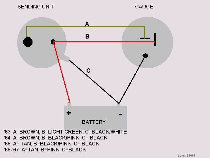
Step 9 once the level sending unit is installed, it needs to be connected to a gauge.t he below wiring should be followed: This assures our gauges' superior qualities and long service lives. 954.463.1075 fax:davie, fl 33314 954.463.1270 kus usa 3350 davie road, suite 203 troubleshooting guide page 3 of 3 7.) to check the sending unit operation, turn all the power to your gauge off, and disconnect the sender wires (black / pink, or black / blue), at the sending unit.
Connect the wire to the sender. Connect the wires on the sender to a multimeter. Fuel water tank sender stainless steel 1 bsp thread fuel water sender s3 screw fit wema sender and gauge wiring diagram find great deals on ebay for wema fuel gauge.
1 0 7 5 • f a x: Power up the gauge by connecting the power wire to the ignition (marked "i") stud and if you obtain a reading then there is a short in the wiring or the sender. To test the ohms on your gauge:
With this sort of an illustrative manual, you are going to have the ability to troubleshoot, stop, and complete your assignments with ease. For over 30 years kus products have been the choice of oems when. If not, the structure won't…
Use this video as a reference.heres a link to. Make sure the power to the gauge is not on. Find great deals on ebay for faria marine fuel gauge.
The sender and gauge must have the same resistance values or the gauge will read incorrectly. Whether you're specifying gauges for the truck, marine, or power generator industry, kus gauges and instruments are built to perform. Determine the proper sending unit length for your tank by measuring from the inside.
Wema fuel sender wiring diagram. Using 18 gauge wire, connect the (i) terminal to a switched +12v source. #2 wema type the wema sender uses a float that rides up and down a sealed dip tube.
This gauge uses a 52mm cutout, and will require 55mm of. Fuel level gauge wiring (figure 4): It includes guidelines and diagrams for various types of wiring strategies as well as other things like lights, home windows, and so on.
Kus products are certified for the nmea 2000 network, ensuring for an easy plug and play, and performance out in the open water. Analogue fuel gauge analogue fuel level gauge for monitoring of fuel tank level. Wire a fuel gauge by first disconnecting the old dysfunctional unit to replace it with a new one.
Next, connect a wire from the float on the fuel tank to the negative terminal of the fuel gauge. Keep tank area free from sparks and flames. Measure the depth of your fuel tank.
If you have access to the wires on the back of the. Disconnect the black wire to the sending unit, at the gauge end. To test senders, the resistance values are shown at minimum and full gauge scales.
31 Fuel Sending Unit Wiring Diagram Wiring Diagram Database

Boat Fuel Gauge Wiring Diagram Wiring Diagram Schema
Boat Gauge Wiring Diagram Wiring Diagram Schema

31 Fuel Sending Unit Wiring Diagram Wiring Diagram Database

Fuel Level Sensor Wiring Diagram Wiring Diagram
64 fuel sending unit wiring question CorvetteForum

[RM_4133] Wiring Diagram For Chevrolet Fuel Gauge Wiring
Vdo Rudder Indicator Wiring Diagram Wiring Diagram

Wema Fuel Sender Wiring Diagram
Fuel Gauge Wiring Diagram Searay
Amp Meter Gauge Wiring Diagram For Boat Wiring Diagram

Faria Marine Fuel Gauge Wiring Diagram Electrical
Fuel Level Sensor Wiring Diagram Wiring Diagram

Wiring Diagram PDF 2002 Mack Truck Wiring Diagram
Wiring Diagram For Boat Fuel Sending Unit Irish Connections


Fuel Level Sensor Wiring Diagram Wiring Diagram
Boat Gauge Wiring Diagram Wiring Diagram Schema


31 Fuel Sending Unit Wiring Diagram Wiring Diagram Database
31 Fuel Sending Unit Wiring Diagram Wiring Diagram Database